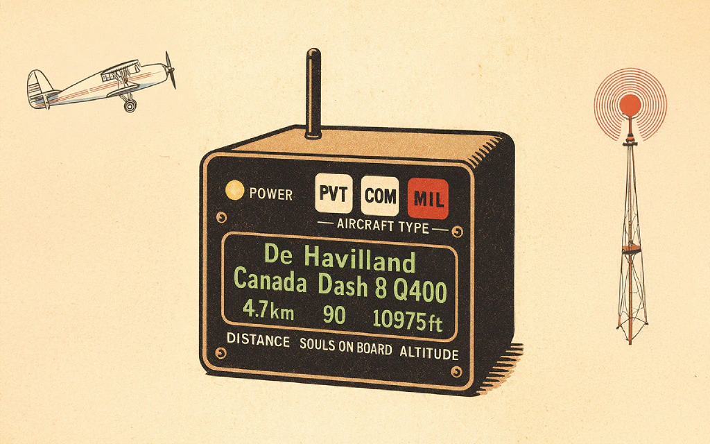
I have an ADS-B node feeding data into the vast network of flight trackers, but it mostly just sits on my roof humming along without any interaction from me. I can, and have, looked at the webpage that shows my local flight data and the planes on a map, but it didn’t quite have the whimsy I was after. I decided a wall-mounted device that displayed the aircraft type closest to my location at any given moment would be a fun build.
What I Used 🔗
- ESP32 development board with external antenna
- 5.5 inch Green Graphic OLED Module from Newhaven Display
- 4 Relay module
- Bambu Lab PLA-CF filament
- 3mm cast acrylic sheet for the faceplate and aircraft type tiles
- 5v LED tape
- A bunch of tools including a X1-Carbon 3D printer, Nomad 3 CNC, and OpenAI Codex for the code
A note about the hardware: I used some pricey tools and a high-end display, but you do not need those to build a functional version of this project. Any decent 3D printer will work; it does not have to be a Bambu Lab. You could also repurpose a project box or even use cardboard. The display was the big splurge, mainly because it’s a newer OLED in this large a size and I wanted to play with it, but almost any display could be adapted depending on your build. Everything else came from Amazon and was relatively inexpensive.
The Seed 🔗
I had an idea in my head and a box of electronics from past projects or impulse buys that never made it past the first step. Before spending any money, which is usually how I kick off a project because they tend to be an excuse for something new, I decided to dig through the reserves and see if I could cobble together a prototype.
Presenting… a prototype:
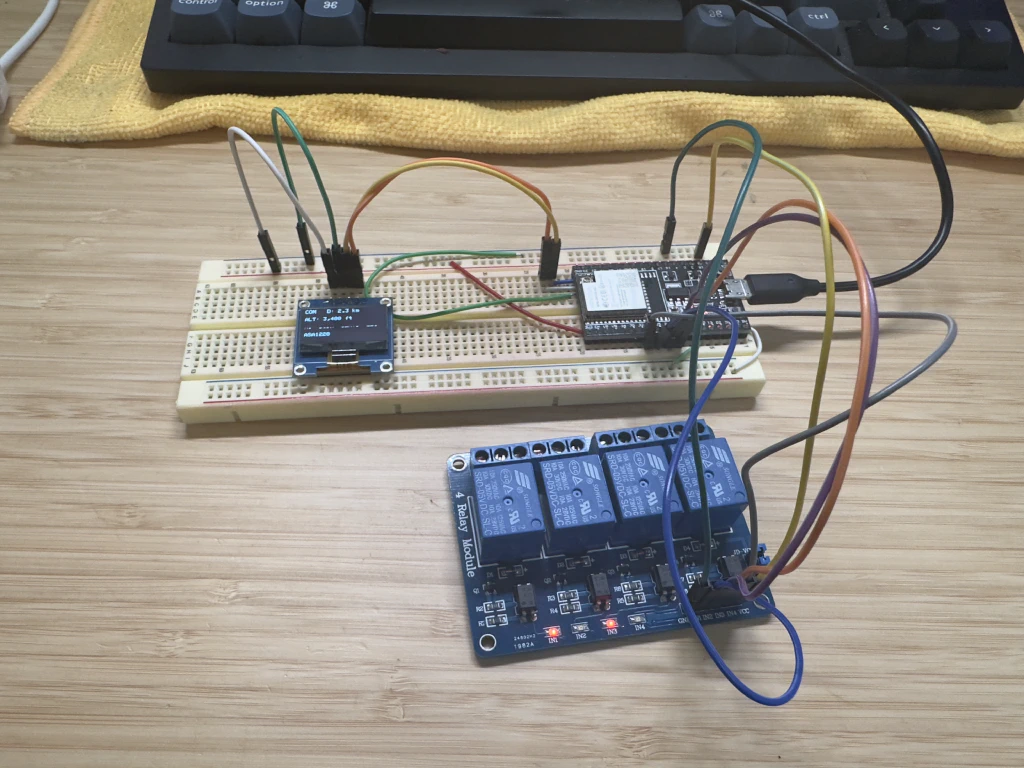
A breadboard with the ESP32 development board, a 0.96” OLED display I picked up from TEMU at some point for about a dollar, and a 4-relay module I purchased back in 2012 for a smart garage door opener project, which was the first electronics project I ever did. Link to a video of said project: Raspberry Pi Smart Garage
The Screen 🔗
Once I had a proof of concept running, that’s when the real fun began, buying new stuff. For me, this entire project revolved around finding a bright display that would be readable at a distance. I typed “large character display” into Google Images and started browsing, eventually landing on this…
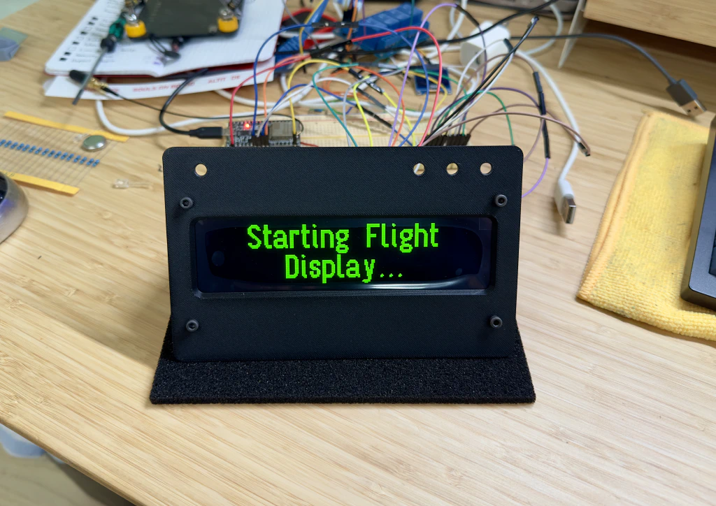
The display I found was a Newhaven Display 5.5 inch Green Graphic OLED Module. It is new to the market, and it is beautiful. Just look at those inky blacks, that super high contrast. I threw it into a 3D-printed test faceplate as quickly as possible so I could stare at it. Take note of all the wires in this photo, we will get to that.
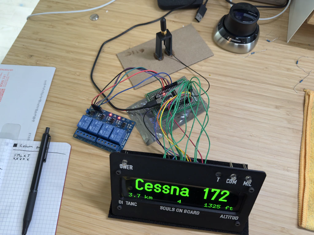
Every green wire coming off the back of the screen is a ground connection. There are a lot of them, and wiring it up was a pain. Out of the 16 pins required, 10 are ground.
The Face 🔗
Up until now, I had been using a 3D-printed faceplate during development, but the plan was always to finish with a painted, CNC-cut acrylic faceplate with engraved lettering. Here’s a screenshot of an early draft. The lettering would come later, and since Fusion doesn’t handle typography very well, the layout process was a bit clunky.
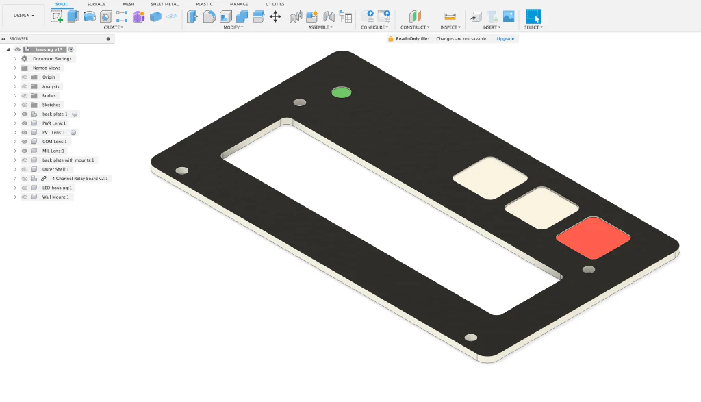
faceplate sans lettering
I designed the part and cut it out so I could paint it and let it cure before moving on to the engraving step. I normally have a hard time letting spray paint cure long enough to harden properly, but that wasn’t a problem on this project. I had a pile of wire and tiny crimp connections to make.
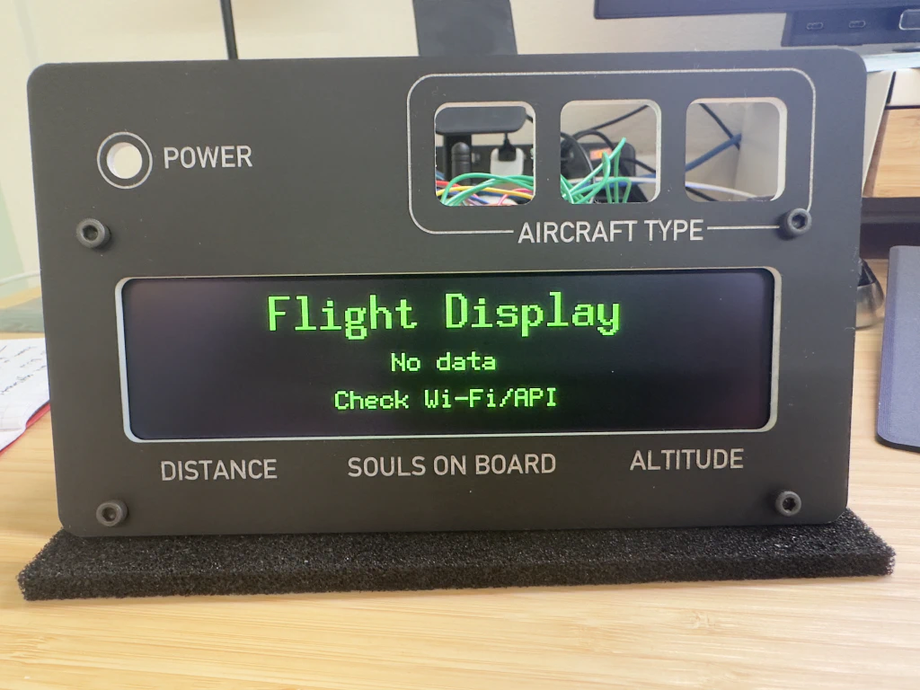
The following picture and video are from my first attempt, where I reversed the order of operations: I painted the acrylic, engraved it, and then cut the faceplate out. That left white edges on the inside of the cutouts, which I didn’t want in the final product. So, when it came time to make the real deal, I changed the order of operations even though it meant having to register the faceplate correctly for the engraving which turned out okay.
The Light 🔗
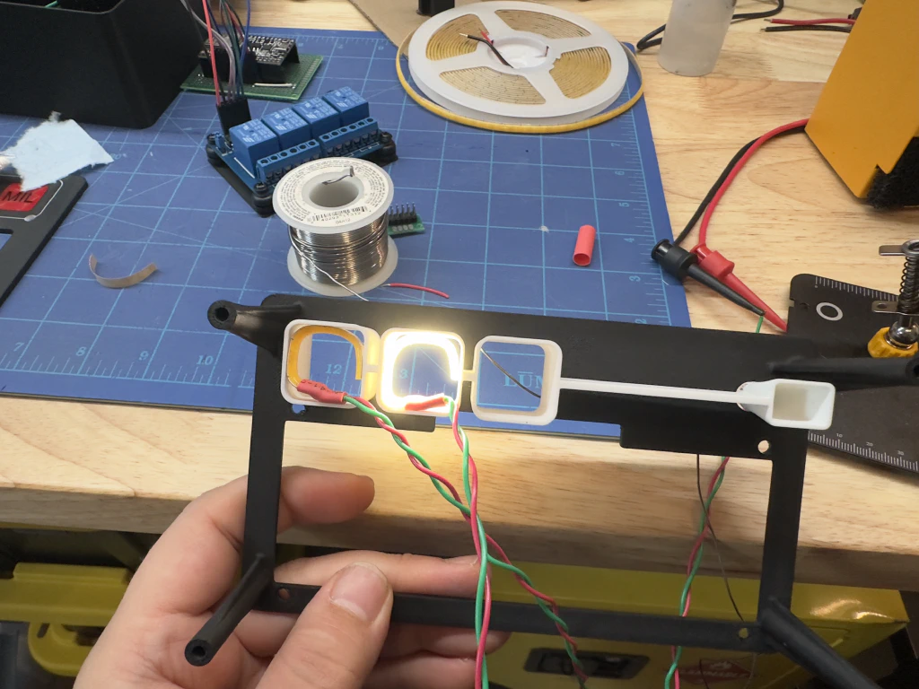
The device has four discrete acrylic panes that are backlit: power indicator, “PVT,” “COM,” and “MIL” panels. I wanted each one to be as evenly lit as possible with no hot spots. A single LED for each would not be enough light to do much of anything, I knew I’d have to use an LED strip, but I wasn’t sure how much I would need for each panel. It wouldn’t matter because I was constrained by the way I designed the light pod, as I call it, and just ended up shoving in as much as I could. Having distance between the light source and backlit area is key to diffusion, a lesson learned on an earlier project that ended up getting featured on hackaday.com ages ago: DEFCON Thermometer.
The keen-eyed among you will notice that the light pods are a few millimeters proud of the joining rib. That’s to allow a press fit into the backing plate shown in the photo with the LEDs lit up.
The Structure 🔗
The unsung hero of this build is the inner backing plate that positions the display, holds the light pods, and allows the housing to be screwed to it via bosses that extend the entire depth of the housing. I initially tried to use heat-set threaded inserts in the bosses because, like with any one-off project, I knew I’d be taking this thing apart to fix or change things. For the 3 mm screws I had on hand, though, there just wasn’t enough material in the bosses for that. Instead, I opted to use coarse-threaded screws that would cut their own threads into the bosses, and I was just careful about how many times I screwed and unscrewed this thing.
Turns out, it wasn’t a problem. This thing probably came apart and went back together dozens of times with no loss of screwability.
And here’s a quick shot of the housing, which is nothing special — just a large open-sided box that took three hours to print.
The Internals 🔗
Because this project was already consuming too much of my time, I decided to stop trying to design mounts incorporated into the housing for the ESP32 and 4-relay module. Instead, I just 3D printed some base plates for both of them and glued them into the back of the housing. Simple and effective. Just don’t glue them in if you are still prototyping… ask me how I know.
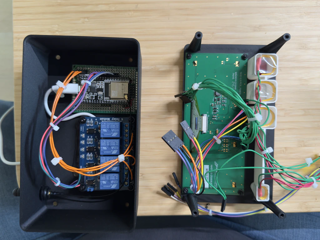
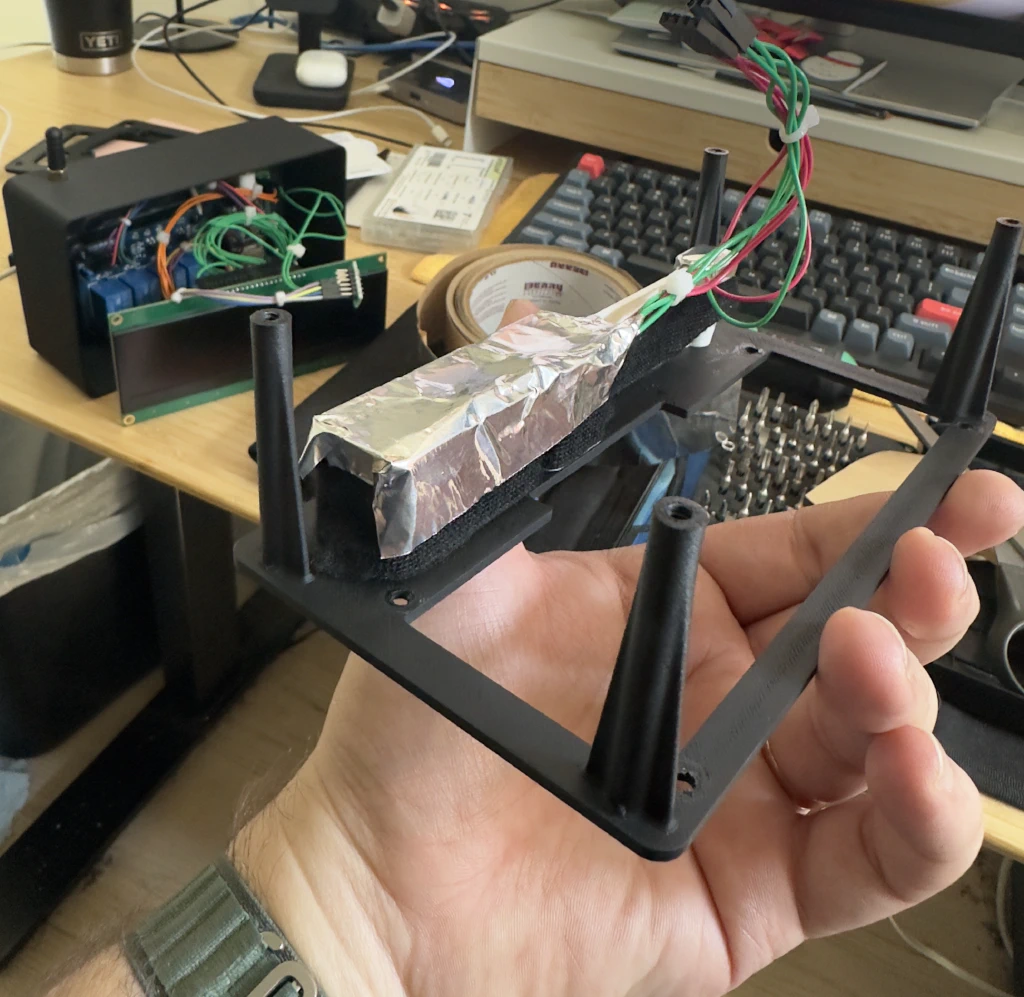
To prevent light from bleeding into neighboring pods, I ultimately painted the outside of the light pods with the same spray paint I used on the rest of the project and covered the back of the light pod with aluminum tape. Below is a picture of a failed attempt at preventing light bleed with cloth tape instead of paint. I just didn’t want to wait for paint to dry, but shortcuts rarely work out.
The Result 🔗
With the paint and glue all dried, it was finally time to hide all my crimes and screw this bad boy together for the last time.
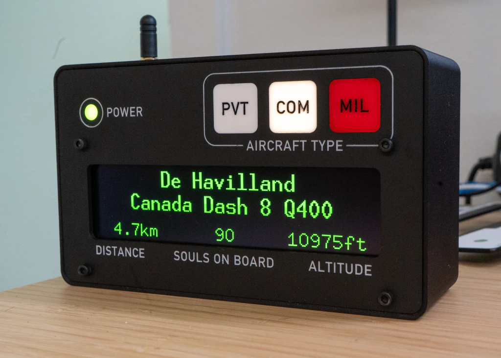
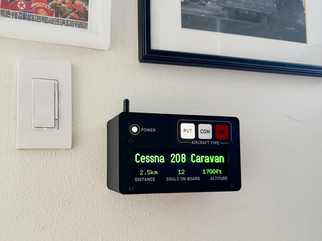
The plan was always to have it wall mounted next to my monitor so it would be in view while I was at my desk. Even though that was the plan from the start, I didn’t include any provisions in the three-hour print of the housing to actually mount it on a wall, and I wasn’t about to reprint it just for that. I could have gone with double-sided tape, but I had always wanted to try embedding magnets into a print. So, I designed a split-frame mount: one half is screwed to the back of the housing, and the other to the wall. The center is open for the power cable passthrough as well as to cut down on material.
I used small magnets around the entire perimeter, and I underestimated how dense this little project was. The magnets were just strong enough. Even though they did hold, I was worried about sag, so I added a small shelf to the bracket. That way the display had something to keep it aligned and prevent sagging.
FAQ 🔗
Where does the “souls on board” figure come from?
It’s just the typical seat count for that aircraft type — not real-time passenger data.
What data source or API are you using?
I started with ADS-B Exchange but switched to a (currently) free API adsb.lol
Can this device work offline with my own ADS-B receiver?
Yes, I’m working on pulling data from my own ADS-B node so it won’t rely on an external API.
How do you distinguish private vs. commercial flights?
Commercial flights show airline callsigns (like AA2122), while private ones usually use N-numbers.
What hardware is used for the display?
It’s a Newhaven Display 5.5 inch Green Graphic OLED Module — I picked it for readability and awesomeness even though it’s pricey.
Why does it make a clicking noise?
The aircraft-type indicators run through relays, and I like the industrial clicking sound they add.
Will there be a build guide and list of materials?
Not exactly, the technical information will be part of the GitHub repository for this project. Anyone who wants to build one like this can have at it, I’d be excited to see what people build.
Are you going to sell these, and how much would they cost?
Not right now, but I might explore a kit version once I finalize using local ADS-B data. If anyone out there is a product person and has experience, I’m all ears.
How do you fetch and parse ADS-B data on an ESP32?
The ESP32 fetches JSON from the API and parses it with the ArduinoJson library.
Why is the OLED display so expensive?
It costs around $70, it’s not necessary but it sure is cool.
Will there be additional features like bearing, course, or transponder codes?
No, but that doesn’t mean others can’t remix this with whatever features make sense for them.
If you’ve made it this far, thanks for showing interest in my project and I hope it inspires you to build something.